Twinkle, Twinkle, Little Star

Did you ever wonder why there are laser beams being emitted from ground-based observatories? No, not to irritate the constellations Lion and Lynx (I had to insert a cat joke). Did you ever get confused about the differences between active and adaptive optics? I did. The short answer: active optics corrects the deformation of the large primary mirror due to external climatic influences and of its own weight; adaptive optics corrects the optical systems for wavefront fluctuations due to the Earth’s atmosphere or as the popular English lullaby refers to: Twinkle Twinkle Little Star.
Optics and the size of primary mirrors have grown since Newton’s 3.3 cm reflective primary mirror in 1688. The glass weighed probably a few ounces and Sir Isaac didn’t have to worry too much about the influences of environmental factors on the resolution power of his telescope, may it be wind, thermal expansion or contraction, or the sheer weight of the mirror. With the thirst of astronomers to build bigger mirrors to gather more light for observation, at some point the size of the mirror became an engineering problem due to the weight of the mirror. For example, the 8.2-meter primary mirror of the Subaru Telescope, the currently largest single-piece telescope in the world, weighs 25 tons or about four elephants. The New Technology Telescope primary mirror of 3.6 meters weights about 6 tons, one elephant. Let’s stick with this monster of telescope for a moment as this was the first telescope where the technology of active optics was implemented. Today, every big telescope uses active optics.
Active Optics
The natural arch enemies of Earth-based optical telescopes are wind, temperature (heat makes material expand and cold makes material contract) and the weight of the mirror itself. All these factors deform the mirror which puts the incoming light out of focus. The heavier the mirror, the more its own weight will deform it. Actuators, little servomechanisms that move something else, support the shape of the mirror and correct any deformations. On the outside edge of the mirror, as more distance from the center means more leverage for equal weight, deformations are bigger. Active optics technology allowed for larger telescopes to be built.
The NTT 3.6 meter (New Technology Telescope at ESO’s La Silla in Chile) is supported by 75 actuators and 24 lateral actuators (which you can see in the image below). They are the little devices with pistons below a mirror to move it up, down or laterally.
NTT Telescope
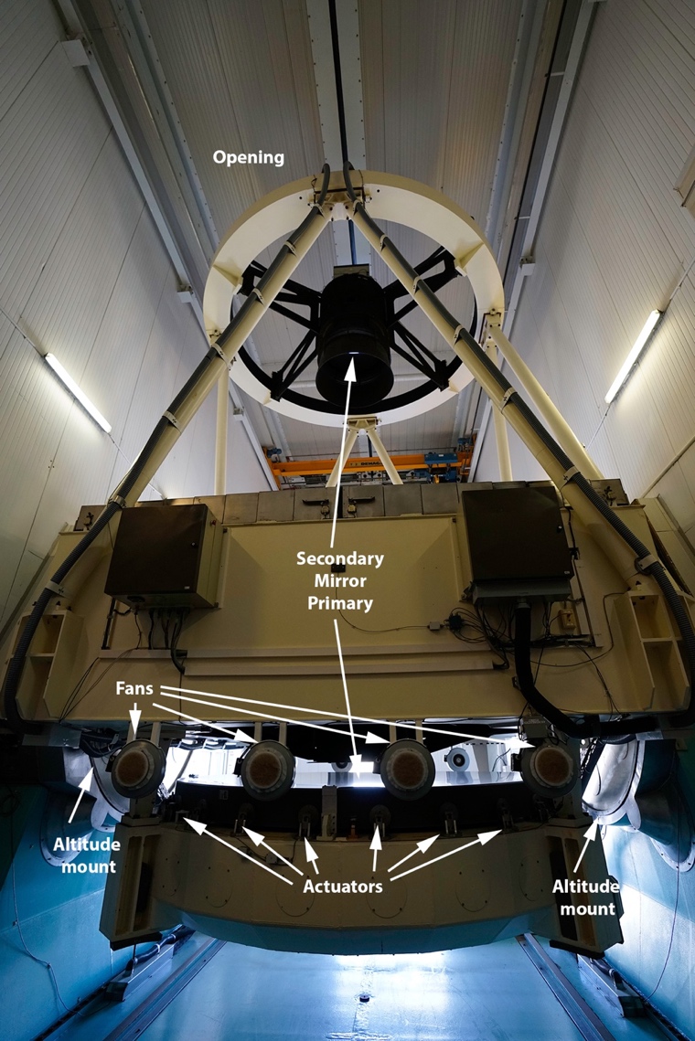
An image sensor provides the telescope operator information about the aberration and every night, the setup process takes about 20-30 minutes to adjust the shape of the mirror. With the advent of active optics, segmented mirrors became possible and have further pushed out the size of telescopes. The 13 largest optical reflecting telescopes in the world have a mirror size of 8.2 meters or larger.
Actuators Close-up

For comparison, the ELT’s (Extremely Large Telescope) 39-meter mirror being built in Chile by ESO consists of 798 segments and 2400 position actuators for active optics.
Adaptive Optics
Now that we are able to build larger telescopes with the help of active optics, we want to improve the resolving power of the optical instruments.
Ground-based telescopes have to overcome astronomical seeing, which is an obstacle of atmospheric distortions when observing distant objects (star twinkling). The first option to overcome atmospheric distortion is to build ground-based telescopes as high an altitude as possible (e.g. Atacama Desert Chile, Mauna Kea, Hawaii, Swiss Alps, Tibet, New Mexico) to decrease the amount of atmosphere above the telescope. There are limits to how high up we can build because we cannot have astronomers start hallucinating due to the lack of oxygen.
We can further improve on the seeing power by measuring atmospheric distortions. There are various ways to measure those perturbations:
- Artificial guide star. This is where the laser beam comes in that you see being “fired” from observatories. The laser point simply acts as point source of light to act as an artificial guiding star. The laser is able to measure the effect of the wave distortions of the atmosphere. For the purpose of laser guided stars, a sodium laser of 20-25 Watts power excites the sodium layer in the mesosphere at around 90 kilometers altitude and create an artificial guide star with a measurement frequency of up to 1000 Hz.
Keck Observatory Laser Guide Star
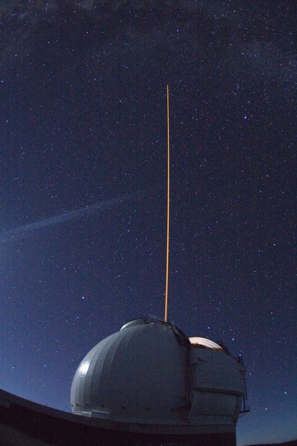
Source: http://www.keckobservatory.org/media/photos/
- Natural guide star. If a natural guide star near the science object of sufficient luminosity can be found, the natural guide star can used to measure distortion. However, there is a limit to natural guide stars. Through a feedback loop between the wavefront sensor and the deformable mirror, instructions are sent to the mirror to adjust the shape continuously to increase resolution. The ELT’s quaternary 2.4-meter mirror will be supported by 8000 actuators. This will be the largest adaptive mirror ever built. Thanks to adaptive optics, ground-based telescopes are able to improve their resolution by an order of magnitude.
Table: Active vs. Adaptive Optics
| Active Optics | Adaptive Optics | |
| Corrects | Ambient Seeing Gravitational deformation Thermal expansion/contraction |
Astronomical Seeing Atmospheric distortions |
| Timescale | Seconds | Milliseconds, microseconds |
| Applications | Primary mirror: Actuators; Telescope housing: Climate controlled; |
Tip-tilt correction Natural guide star Laser-guided star Wave front sensor Beam splitter, deformable nth mirror, computing power |
Below you can see improvement of observations by ESO’s VLT (Very Large Telescope) and its performance versus the space-based Hubble telescope.
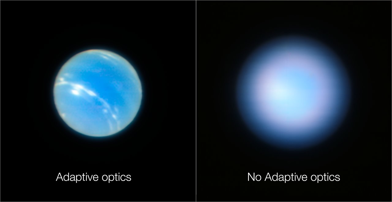
Credit: ESO/P. Weilbacher (AIP)
Source: https://www.eso.org/public/usa/images/eso1824b/
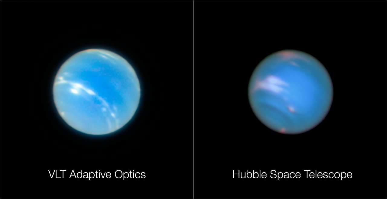
Credit: ESO/P. Weilbacher (AIP)/NASA, ESA, and M.H. Wong and J. Tollefson (UC Berkeley)
Source: https://www.eso.org/public/usa/images/eso1824c/
We keep pushing the boundaries of Earth-based optical instruments with the help of technology and will have to write a new lullaby: “Focus, Focus, Little Star”.
References:
ESO website:
ELT specifications
Technical details NTT
Gloess, R. et al.: Ultra-High Precision Positioning Actuators to Align Mirror Segments in the ELT Telescope
Lemaitre, Gerard R., (2012): Optical Design and Active Optics Methods in Astronomy; OPTICAL REVIEW – The Japan Society of Applied Physics
Milton, Mark N. et al.: Real-time atmospheric turbulence profile estimation using modal covariance measurements from multiple guide stars. Center for Astronomical Adaptive Optics, Steward Observatory
Watson, J.: Tip-Tilt Correction for Astronomical Telescopes using Adaptive Control